Avata in the Dark
Turning night-flight headaches into a product-style side project. My journey designing, testing, and iterating an LED mount for the DJI Avata.
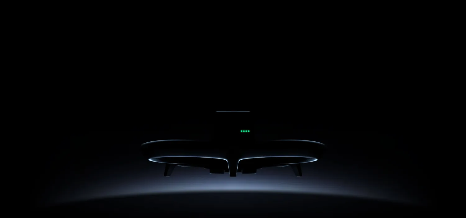
In 2022, DJI released the Avata drone. It burst onto the scene as a game-changer in the consumer FPV drone world, offering an immersive flight experience with DJI’s renowned UX and safety features. Designed to be nimble and durable, the Avata truly shines when it comes to indoor flight. Its compact size and built-in propeller guards make it inherently robust, allowing confident navigation through tight spaces and reducing the risk of damage from inevitable bumps and scrapes. The visual positioning system provides exceptional stability and precision even without GPS signals, enabling it to maintain its position accurately in cluttered indoor environments and making it a favored choice for capturing dynamic interior footage.
Flying in Darkness
The problem starts when twilight descends or when you simply float into a window-less, light-less room – piloting the drone through dim corridors can feel as unpredictable as chasing fireflies. The optical sensors are starved of contrast and reference points, leaving the drone wobbling each time you try to hover between obstacles, until it inevitably hits something and crashes.
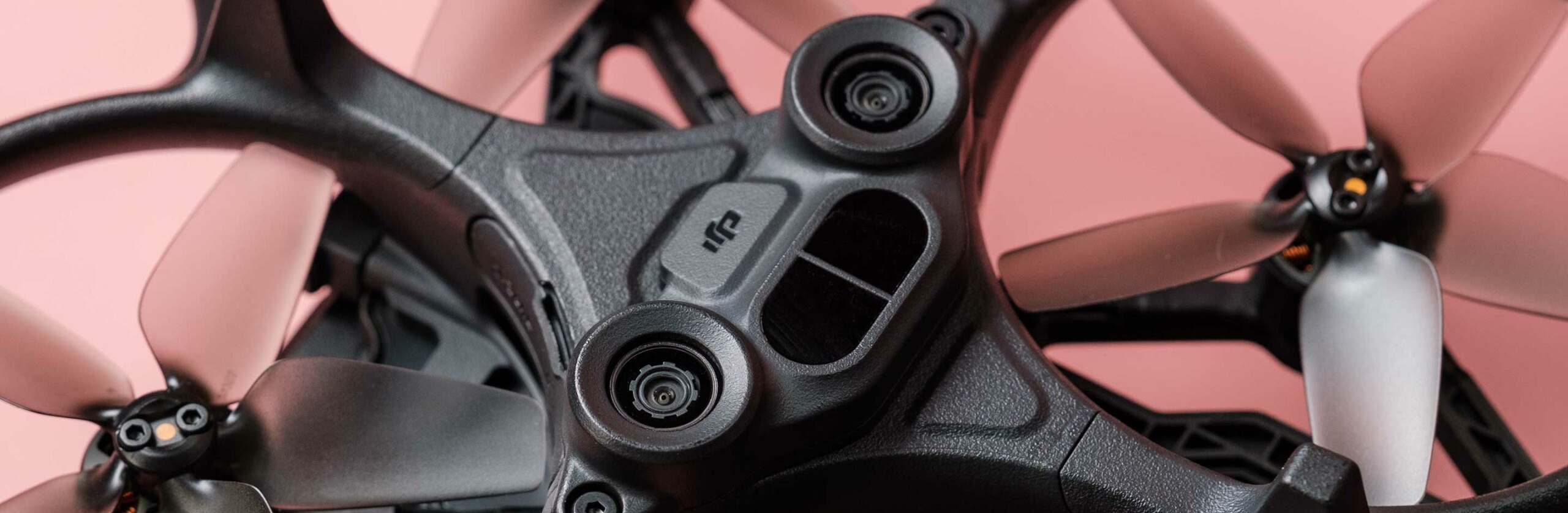 VPS components of the DJI Avata
The solution seemed obvious – more light equals better stability. By mounting LEDs on the drone, I could feed the vision sensors a steady stream of visual cues, transforming low-light missions into smooth cinematic flights.
I started off with some ad-hoc market research: I scoured forums, DJI groups, Thingiverse, and online shops for Avata LED mounting solutions. A few options existed but they were overpriced, bulky, or poorly reviewed. Classic “build vs buy” moment. With no viable off-the-shelf choice, I went hands-on – dusted off my 3D modeling skills and started designing a custom LED mount for my exact needs.
Choosing the Right LED
First things first, I needed a capable LED light that I could design a mount around and attach to the drone. I scanned Amazon and AliExpress for candidates that comply with a few simple prioritized requirements:
- Illumination – strong enough to light up dark halls and corridors.
- Lightweight – minimal impact on drone flight time.
- Small profile – maintain the drone’s cross-section and have minimal effect on propeller thrust.
- Battery capacity – enough to maintain illumination for at least one drone-battery cycle (~20 minutes).
I ended up with two main candidates to choose from:
- Firehouse ARC V
- BRDRC Strobe 3-LED
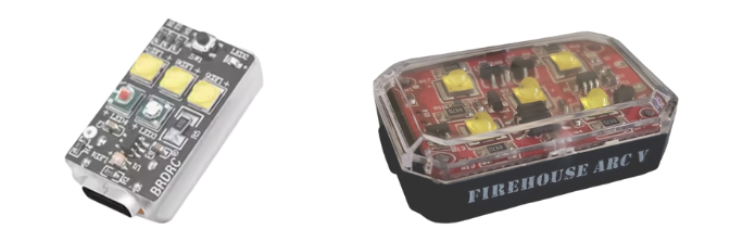 BRDRC (left) vs. Firehouse (right)
As always, when tasked with a tough decision – the scorecard method is your friend. I listed all features that mattered to me in a table, assigned weight factors based on my priorities, and scored each candidate with a 1-5 rating based on its compliance/performance:
| Category | Weight | Firehouse | Score | Weighted | BRDRC | Score | Weighted |
|---|---|---|---|---|---|---|---|
| Price (1 unit) | 30% | US$ 33 | 2 | 0.60 | US$ 8 | 5 | 1.50 |
| Weight | 20% | 13 gr | 3 | 0.60 | 6 gr | 5 | 1.00 |
| Illumination | 15% | x5 White LEDs | 5 | 0.75 | x3 White LEDs | 3 | 0.45 |
| Size & profile | 15% | 38 x 25 x 13 mm | 3 | 0.45 | 28 x 16 x 10 mm | 5 | 0.75 |
| Battery (Steady-on) | 10% | 120 mins | 5 | 0.50 | 45 mins | 2 | 0.20 |
| Charger socket | 5% | USB-C | 5 | 0.25 | USB-C | 5 | 0.25 |
| Charge indication | 5% | No | 2 | 0.10 | Yes | 5 | 0.25 |
| Total | 100% | — | 3.25 | — | 4.40 |
With everything factored in, going with BRDRC was a no-brainer. It’s smaller, lights and offers significantly better bang-for-buck – though I did sacrifice some illumination compared to the Firehouse. That’s an acceptable trade-off, given that most low-light flights are planned to be indoors.
Figuring Out a Mounting Solution
Now that I’ve chosen an LED light for my solution (I ordered 6 strobes, more than enough to begin with), I could move ahead with figuring out how to actually mount the LED onto the drone in the most efficient way.
The Requirements
Before opening my 3D-modeling app I wrote a mini-PRD – nothing fancy, just a bulleted list of “must haves” ranked by priority. That helped me organize my thoughts, stay honest about the use-case and cut down on 3D-printing iterations. Here’s the shortlist my LED mount had to meet:
- 3D-printable – relatively simple design that can be 3D-printed easily at home.
- Durable – just like the drone itself, it’s expected to take a few hits.
- Lightweight – minimal impact on drone flight time.
- Slim design – to minimize protrusion outside of the drone’s profile.
- Detachable – for two main reasons:
- Avoid flying daylight missions with extra dead weight (no flight-time reduction).
- Enable flying long low-light missions by easily swapping LEDs when they’re out of juice (improves field usability and reduces downtime).
Mini-KPI plan: total added weight, impact on flight time, and whether the Avata can still hover stably in a dark hallway. Those would be my success metrics for this prototype.
Mountable Surfaces
The initial step before getting down to actual design work would be deciding which part of the drone fuselage the LED mount should actually attach to. Inspecting the drone’s bottom side reveals two potential areas for affixing an LED light:
- Attached to the relatively-wide & flat surface right below the VPS components.
- Attached to the diamond-shaped slot formed between the outer sides of the rotors.
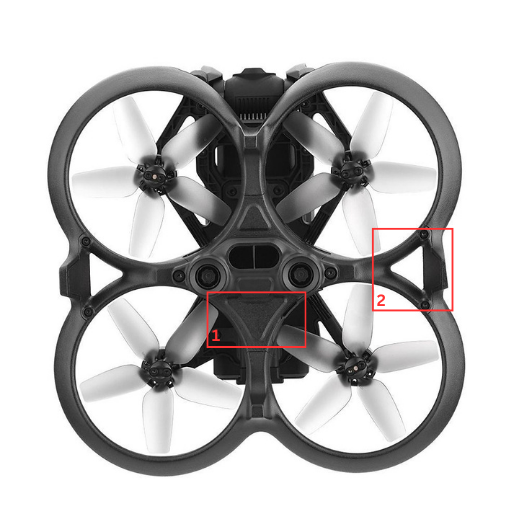 Bottom view of the Avata drone with marked options for mounting
I decided to move forward with option #2 for these reasons:
- The diamond-shaped slot provides depth for significantly more robust mounting methods.
- The depth also means that LEDs can be mounted closer to the fuselage, helping to keep the LEDs tighter with the assembly and maintaining the drone’s slim profile.
- The slots appear on both sides of the fuselage, making it favorable for mounting x2 mounts (with x2 LED lights).
- It’s much safer to fly low-light missions – even if one LED fails, you could still finish your mission as planned with the other functioning LED, or at the very least significantly increase your odds of getting the drone back safely in the dark.
3D Measurements
Next, after deciding what component/part of the drone we are going to latch onto, we need to accurately measure that area of the drone in order to properly design a mounting solution that actually fits well. For hobbyists like me, the usual go-to tool would be a simple caliper, however, if I had the actual 3D model of the drone accessible in my modeling app, it would make life significantly easier. Luckily, a quick search in some 3D repositories landed me in this Thingiverse webpage featuring the DJI Avata body scanned for us by the good soul goshes.
I loaded the scanned object into my 3D modeling app (SolidWorks) and extracted the exact contour I needed for my mounting solution to fit. This little trick with 3D scanned objects is extremely useful and saved me at least a few iterations of caliper measuring, printing and testing the mount fit vs. real drone body.
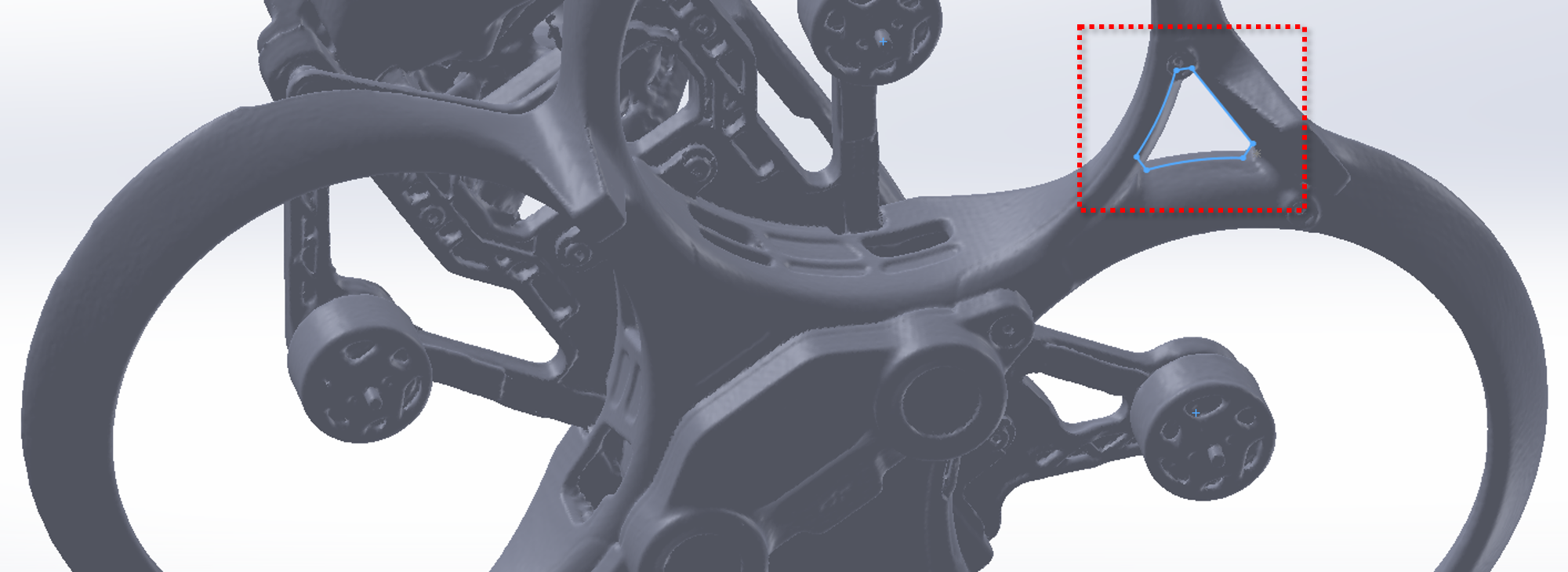 Measurement sketch drawn on a 3D model of the Avata drone
The Design
With the goal of complying with all requirements specified above, I finally got down to the actual 3D modeling step. Using the measurement sketch from before, I started by designing the core of the mount (diamond-like shape that fits in the propeller-guards slot), and around it I derived a few key elements:
- Base plate – this would be the surface area to which I’d attach the LED. I want it to be slim and match the actual surface area my LED takes (minimize impact on propeller thrust).
- Flexible arms – these elements will continue upwards from the core, they will be relatively thin to enable flexibility as the mount is pushed into the slot in the drone body.
- Latch teeth – these elements will merge to the top of the flexible arms and will allow locking the mount into place when fully inserted into the diamond-shaped slot.
- Arm extensions – this is the top-most part of the flexible arms, it will extrude above the propeller-guards to enable a human operator to flex the arms and detach the mount from the drone body.
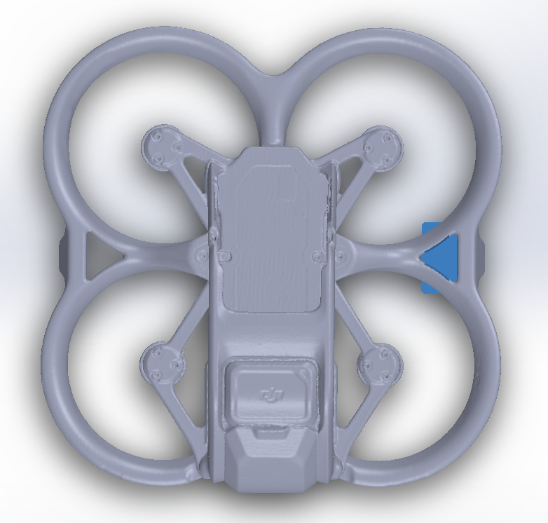
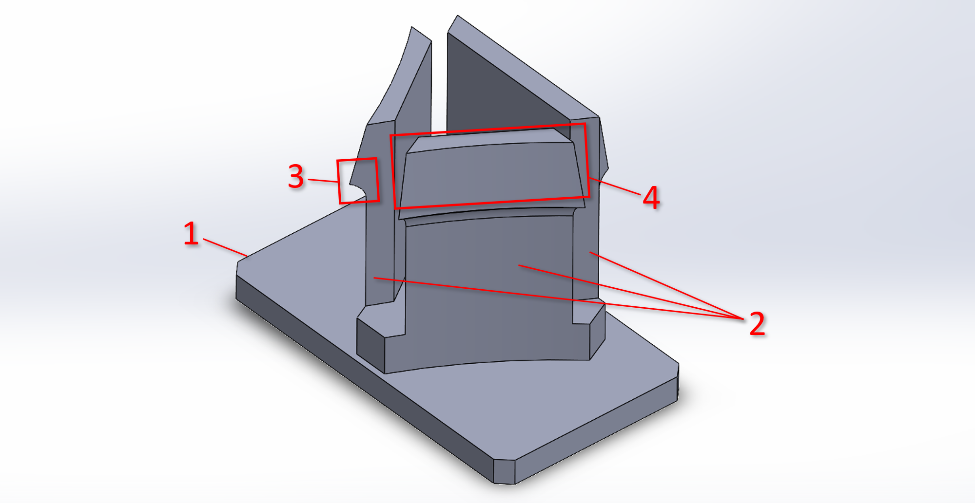 LED mount design
Here are a few more pictures of the assembly:
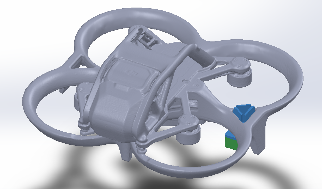 Mock BRDRC LED (green) attached to the drone with our custom mount (blue)
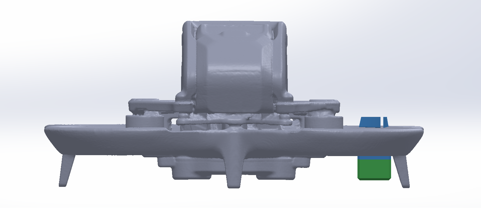 Front view showcasing the slim profile of a mock BRDRC LED (green) mounted on the drone
 Top view showcasing the minimal surface area of the mount over the properllor-thrust direction
Printing the LED Mounts
With the 3D model wrapped up and saved as an STL, I headed over to a friend’s place to fire up his 3D printer and crank out a few test pieces. At this stage there are two big decisions that can make or break the print – what material you’re going to use, and how you’re going to orient the part on the bed.
Printing Material
When it comes to hobbyist 3D printing, it usually comes down to PLA or PETG. PLA is kind of the “default” – it prints easily, doesn’t warp much, and is perfect for quick prototypes or little decorative parts. PETG, on the other hand, is a bit tougher (literally). It needs higher temps and a bit more fine-tuning to avoid stringing, but it pays off with parts that are stronger, more flexible, and way better at handling moisture or outdoor use. I’ve found that once you get the hang of PETG, it’s awesome for anything fsunctional, while PLA still wins for quick, clean prints with zero fuss. For the first run I treated the print like an MVP: go fast, validate fit, then iterate. PLA gave me a quick, clean prototype. Once the geometry is proven, PETG can be the “production” version with more durability.
Orientation
Since our design uses flexible arms, it’s quite clear the highest stress runs along the length of those arms. That means the way you orient the part on the print bed can make a huge difference in how strong (or weak) it ends up. By lining up the arms so the layer lines run along them instead of across them, you give the print way more resistance to snapping when flexed. It’s one of those little tweaks that doesn’t take any extra time but pays off big when you start actually using the part.
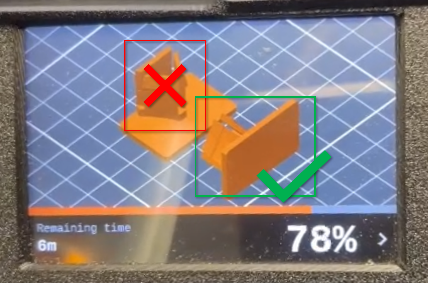 Recommended orientation for 3D printing
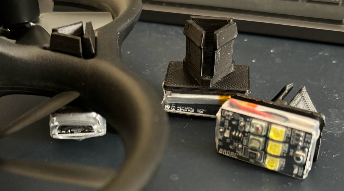
Attachment
Now with a few printed models and the LEDs at hand, I needed to attach them together – this was easily done by using outdoor-rated double-sided tape. Good quality tape designed to work in heat and moisture conditions will hold forever (not much strain on it since our parts are extremely lightweight). It is actually very likely to outlast the drone itself.
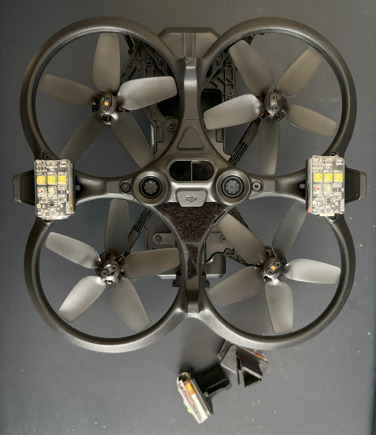
Here are some final pictures of the LEDs and mounts:
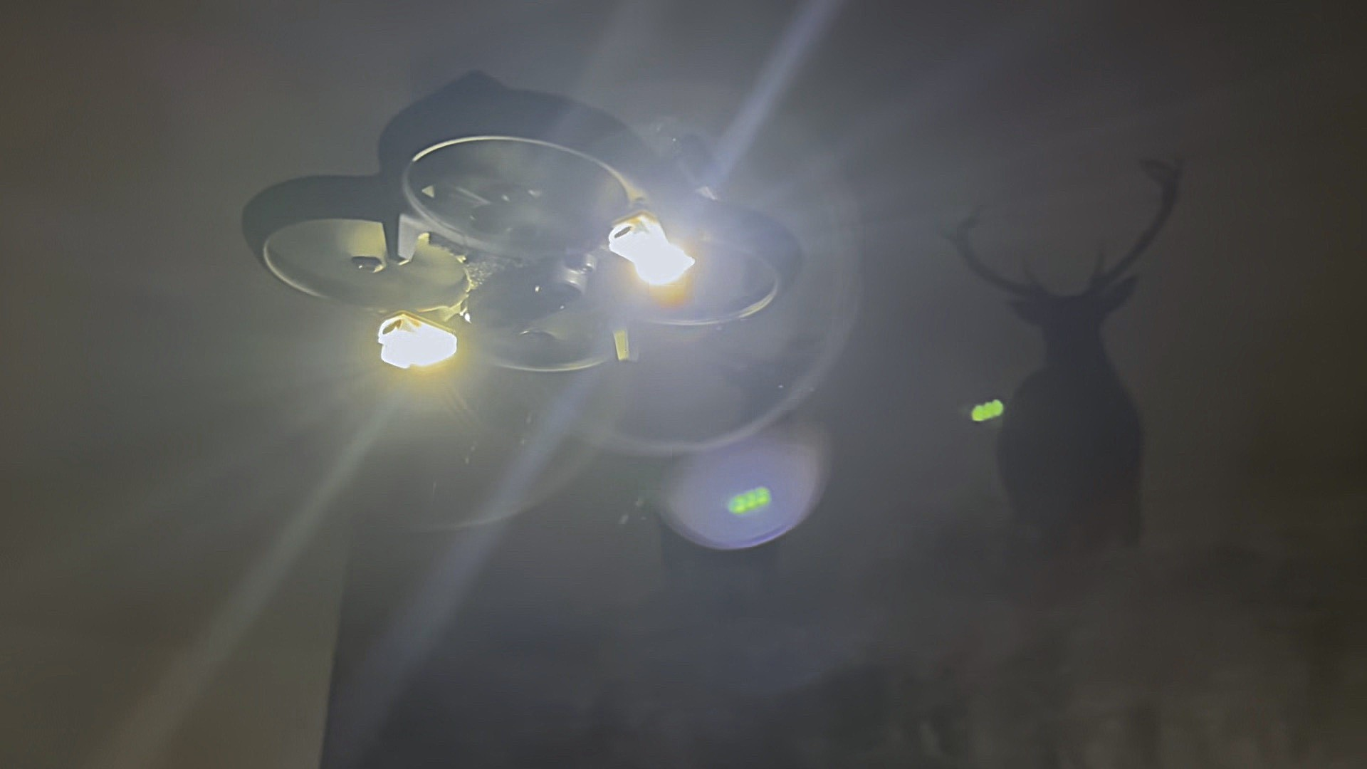
Final Thoughts
Like any good prototyping, there’s a plan for next version – testing PETG prints, different LED angles for better spread, and maybe a solution for controlling the LEDs remotely. You can find the STL file for 3D printing in my github repository here (where I’ll likely upload future revisions as well).
That’s about it, enjoy flying!